356282 | Pentair SuperFlo VS / VST WhisperFlo VS / VST Motor Drive Kit
356282 | Pentair SuperFlo VS / VST WhisperFlo VS / VST Motor Drive Kit
SKU#: 356282
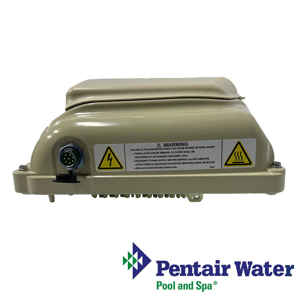
356282 Pentair Motor Drive Kit for SuperFlo VS/VST, SuperMax VS and WhisperFlo VS/VST Variable Speed Pumps Systems after October 2020
$649.99


-
Product Details
About this product
Description
The pump features a variable frequency drive capable of controlling the motor speed according to programmed settings. This provides flexibility in meeting your filtration system’s specific needs. The pump is intended to run at the lowest speeds needed to maintain a sanitary environment and, at the same time, minimize energy consumption. Factors such as pool size, the presence of additional water features, type of chemicals used to maintain sanitary
conditions, and local environmental factors will impact optimal programming to maximize energy conservation.
Determining the optimal settings and programming for your pool may require some trial-and-error.Highlights
External Control
The pump can be externally controlled via digital inputs using the Digital Input Wiring Kit (P/N 353129Z - Almond)
the RS-485 Automation Wiring Kit (P/N 356324Z - Black). See External Control via Digital Inputs, page 6 or External Control via RS-485, page 5. When connected to external controls, the pump will prioritize commands as follows:
RS-485 > Digital Inputs > Drive Programmed Schedules Refer to your control system manual for further details
on how to connect and program your pump with your control system.Operation
Setting the Clock and Pump Address
Using the Default Schedule
Programming Custom Schedules
Program Priorities (Non-External Control)
Priming the Pump
Priming Adjustment
Operating the Pump While Running
Programming Quick Clean
Keypad Lockout
Factory Reset
Operating the Pump in Flow Mode
Flow Mode Setup and Configuration
Adjusting Flow SettingFeatures
Brand Information

Founded in 1966, Pentair has engineered water solutions to filter, clean and sanitize water to its purest state, while automation equipment makes it all easy to control from anywhere so that you can truly enjoy your pool and spa.
Visit Manufacturers Website -
Specifications
Fault Code Description 21 Communication link between HMI and motor control has been lost 1A Power Module over current detected 17 Phase Current Offset out of range 16 Phase Current Imbalance detected 0F Absolute AC under voltage detected 02 Absolute Phase current limit exceeded 08 Absolute Diode Bridge temperature limit exceeded 04 Absolute Power Module temperature limit exceeded 06 Absolute Power Factor Correction (PFC) temperature limit exceeded 09 DC bus over voltage detected 0A DC bus under voltage detected 19 Motor start failure 0b AC Voltage maximum exceeded 21 – Communication Link between the HMI and Motor Control has been lost: Remove the top cover from the drive and inspect the jacketed wire on the backside of the keypad. Ensure that the 5-pin connector is properly plugged into the socket and that there is no damage to the cable.
02 – Power Module Over Current Detected: If this error displays multiple times, then there may be a problem with the pump’s rotating assembly. Disassemble the pump (see Pump Disassembly on page 16) and inspect the impeller and shaft seal for problems.
0F – Absolute AC Under Voltage Detected: Indicates that the supply voltage has dropped below the operating range of 99v. This could be caused by normal voltage variation and will clear itself. Otherwise there could be excess voltage drops caused by improper installation or improper supply voltage.
19 – Motor Start Failure: Could indicate a locked rotor. Verify the fan at the rear of the motor is free of debris. Attempt to break up impeller blockages by rotating the motor shaft through the fan cover using a hex-key. If this does not work the pump may need to be disassembled (see Pump Disassembly on page 16).
0b – AC Voltage Maximum Exceeded: Indicates that the supply voltage is exceeding the operating range of 251v.
1A,17,16, 02, 08, 04, 06, 09, 0A – Internal Errors: These errors can occur based on operating conditions and the required self-diagnostic safety software. If they do not clear after multiple restart attempts the drive should undergo a hard power cycle. Disconnect power at the circuit breaker long enough for the keypad LEDs to turn off. If the error continues to appear after power is reconnected, the drive may need service -
Q/A
No Questions
Log in
Create a Free Account
Please fill out sign-up form
Sign up with your social media account
Or
Fill out sign up form
Why create an account
Sign up with your social media account